
Frequency Converter SD2S
Powerful, flexible and compact – these words describe the drive amplifier SD2S by SIEB & MEYER. Using the available drive functions synchronous and asynchronous motors with speeds up to 480,000 rpm can be driven by SD2S, especially in respect of a low motor heating in high-turning motors with small rotor volume. Furthermore, small motor temperatures are the basis for a high machining quality.
Highlights

The Specialist for High-speed Applications
Depending on the application, the operation can be carried out with or without encoder. For the operation with an encoder SD2S offers the possibility to evaluate the common encoder systems existing on the market.
SD2S is connected to the higher-ranking control via analog reference values (+/-10 V), digital I/Os, RS232, USB, CAN bus, PROFIBUS*, PROFINET* or EtherCAT (CoE)**.
* Via gateway
**CoE=CAN over EtherCAT

Easy but Robust
Additionally to the basic characteristics in respect of a low motor heating SD2S offers two drive functions characterized by an easy parameterization and a robust operation for applications up to 120,000 rpm. For asynchronous motors the drive function V/f-PWM is used. By means of the V/f characteristic curve the user can carry out the graphically aided parameterization of the motor. As using the V/f characteristic curve is an established form of motor parameterization for example in grinding applications, the user can take advantage of the experience gained in this field.
The SVC drive function (Sensorless Vector Control) is provided for synchronous motors and is based on the equivalent circuit diagram usually found in the motor data sheet. SVC allows 4-quadrant operation of high speed synchronous motors and generators so that SD2S can be used for high speed applications such as turbo blowers or turbines for utilization of process energy.

The Interfaces of SD2S
- Mains supply (DC)
- 24 V-Logic supply
- Parameterization and diagnosis
- 6 digital inputs and 4 digital outputs
- Safety integrated "STO": Restart lock to meet category 4/PL e according to EN ISO 13849-1:2015 and EN 61508:2010 SIL3
- Encoder inputs and outputs (Puls-direction signals)
- Encoder inputs and outputs (measuring system simulation)
- Analog reference value interfaces: +/-10 V
- Resolver inputs
- Thermal contacts
- Universal motor encoder interface: Encoder / linear scale(TTL or Sin/Cos), EnDat, Hiperface, SSI, Hall effect sensor, linearer Hall sensor, magnetoresistive sensor
- SERVOLINK 4 via optical fiber connector
- 2 x Motor connection for synchronous / asynchronous spindles, linear motors and rotary motors
EtherCAT, PROFIBUS and PROFINET via gateway
Drive Functions and Safety Functions

Technology Functions for Grinding Applications
Multi parameter sets
The flexibility of grinding machines largely depends on the possibility of a fast and simple use of grinding spindles. The feature of saving up to 64 motor parameter sets in the drives enables the variable operation with different motors. The number of parameter sets can be encoded via the digital inputs or alternatively via the provided data interfaces.
Gap eliminator / Load indicator
The load indicator is a standard function that is implemented in all devices of series SD2x. The function is used to monitor the status of the active current of spindles. If a preset motor workload is exceeded, the function generates a message. In contrast to acoustic emission sensors, this function evaluates the actual active current of the motor. This is why a very high precision is possible when detecting the load changes of the motor. A load created by e.g. a touch between tool and work piece causes a significant rise in the motor current. Such a load is detected by means of the load indicator. This makes additional external components obsolete.
The load indicator can be used:
- as an indicator for tool breakage
- as a main system in dressing processes
- for a detection with micrometer precision when the tool touches the work piece (gap / touch)
- as an indicator for a necessary tool change due to abrasive wear
- as an indicator for a necessary feed rate reduction (productivity increase by reducing the air-cutting time)
- for a fully automatic adjustment
- as a substitute for acoustic sensor technologies (acoustic emission)
Software for Initial Operation and Parameterization: drivemaster2
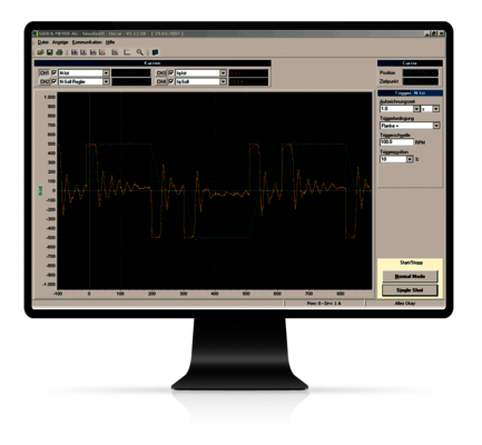
The oscilloscope function allows optimization of the axes in the machine via the drive-setup-tool without additional measuring equipment.
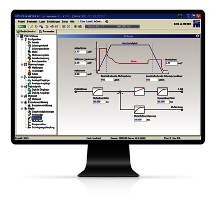
The clear design of the software allows intuitive parameterization via graphics and block diagrams. The „Parameter-Wizard“ guides the user step-by-step through the system configuration and allows intuitive setup of the device via help messages and comments.

Operation Unit (optional)
LCD status display for the indication of operating data:
- Parameters
- Reference / actual speed
- Load display
- Active spindle
- Error messages
LED status displays for:
- Ready for operation
- Load message
Technical Specifications of Frequency Converter SD2S
| Device type | Rated power1 | Rated current | Peak current/time | Max. output voltage1 | HxWxD (mm) | Weight | Cooling |
|---|---|---|---|---|---|---|---|
| Compact devices - 1 x 50 VAC mains voltage | |||||||
| 0362X40DA | 330 VA | 10 Arms | 14 Arms/5 s | 3 x 45 VAC | 249 x 70 x 188 | 2.5 kg | Air |
| Compact devices - 1 x 110 ... 230 VAC mains voltage | |||||||
| 0362X40DC | 1.5 kVA | 10 Arms | 14 Arms/5 s | 3 x 200 VAC | 249 x 70 x 188 | 2.5 kg | Air |
| 0362X40EC | 1.5 kVA | 10 Arms | 28 Arms/2 s | 3 x 200 VAC | 249 x 70 x 188 | 2.5 kg | Air |
| Compact devices - 3 x 200 ... 230 VAC mains voltage | |||||||
| 0362X41EC | 3.8 kVA (6.9 kVA2) | 20 Arms | 28 Arms/5 s | 3 x 200 VAC | 253 x 104 x 188 | 3.5 kg | Air |
| 0362X41IC | 3.8 kVA (6.9 kVA2) | 20 Arms | 56 Arms/2 s | 3 x 200 VAC | 253 x 104 x 188 | 3.5 kg | Air |
| Compact devices - 3 x 200 ... 480 VAC mains voltage | |||||||
| 0362X40EF | 4.3 kVA | 7 Arms | 28 Arms/5 s | 3 x 410 VAC | 249 x 70 x 232 | 2.6 kg | Air |
| 0362X41EF | 9.7 kVA | 14 Arms | 28 Arms/5 s | 3 x 410 VAC | 253 x 104 x 188 | 3.5 kg | Air |
| 0362X41IF | 9.7 kVA | 14 Arms | 56 Arms/2 s | 3 x 410 VAC | 253 x 104 x 188 | 3.5 kg | Air |
| 0362X49IF3) | 9.7 kVA | 14 Arms | 56 Arms/0,4 s | 3 x 410 VAC | 279 x 90 x 220 | 3.9 kg | Air |
| 0362X45EF | 15.9 kVA | 23 Arms | 28,3 Arms/5 s | 3 x 410 VAC | 390 x 181 x 178 | 7.8 kg | Air |
| 0362X45IF | 20.8 kVA | 30 Arms | 56,6 Arms/2 s | 3 x 410 VAC | 390 x 181 x 178 | 7.8 kg | Air |
| 0362X46IF | 24.2 kVA | 35 Arms | 56,6 Arms/5 s | 3 x 410 VAC | 460 x 190 x 220 | 13.7 kg | Air |
| 0362X46LF | 30.5 kVA | 44 Arms | 70,7 Arms/5 s | 3 x 410 VAC | 460 x 190 x 220 | 13.7 kg | Air |
| 0362X48MF | 55.4 kVA | 80 Arms | 113 Arms/5 s | 3 x 410 VAC | 429 x 272 x 265 | 19 kg | Air |
| 0362X48OF | 55.4 kVA | 80 Arms | 113 Arms/5 s | 3 x 410 VAC | 429 x 200 x 262 | 15 kg | Water |
X = 1: CAN-Bus
X = 2: EtherCAT and CAN-Bus
1) Rated power and max. output voltage for mains voltage/supply voltage (in italic)
2) Output power at three-phase mains
3) NRTL/CSA certified
Technical Specifications of Frequency Converter SD2S light
without Interfaces for Measuring Systems, with CAN bus
| Device type | Rated power1 | Rated current | Peak current/time | Max. output voltage1 | HxWxD (mm) | Weight | Cooling |
|---|---|---|---|---|---|---|---|
| Compact devices - 1 x 110...230 VAC mains voltage | |||||||
| 0362120DC | 1,5 kVA | 10 Aeff | 14 Aeff/5 s | 3 x 200 VAC | 249 x 70 x 188 | 2,5 kg | Air |
| 0362120EC | 1,5 kVA | 10 Aeff | 28 Aeff/2 s | 3 x 200 VAC | 249 x 70 x 188 | 2,5 kg | Air |
| Compact devices - (3)1 x 110...230 VAC mains voltage | |||||||
| 0362121EC | 3,8 kVA (6,9 kVA2) | 20 Aeff | 28 Aeff/5 s | 3 x 200 VAC | 253 x 104 x 188 | 3,5 kg | Air |
| 0362121IC | 3,8 kVA (6,9 kVA2) | 20 Aeff | 56 Aeff/2 s | 3 x 200 VAC | 253 x 104 x 188 | 3,5 kg | Air |
| 0362129EC3) | 3,8 kVA (6,9 kVA2) | 20 Aeff | 28 Aeff/1 s | 3 x 200 VAC | 279 x 90 x 220 | 3,9 kg | Air |
| Compact devices - 3 x 200...480 VAC mains voltage | |||||||
| 0362121EF | 9,7 kVA | 14 Aeff | 28 Aeff/5 s | 3 x 410 VAC | 253 x 104 x 188 | 3,5 kg | Air |
| 0362121IF | 9,7 kVA | 14 Aeff | 56 Aeff/2 s | 3 x 410 VAC | 253 x 104 x 188 | 3,5 kg | Air |
1) Rated power and max. output voltage for mains voltage/supply voltage (in italic)
2) Output power for three-phase mains
3) NRTL certified
News
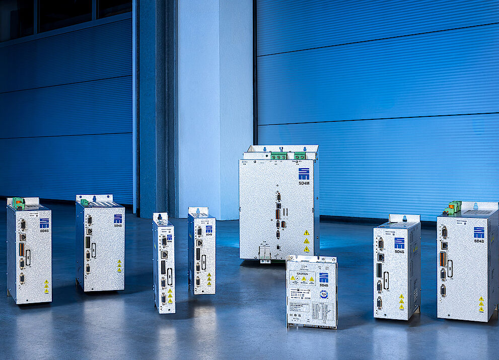
A Drive Controller for All Purposes
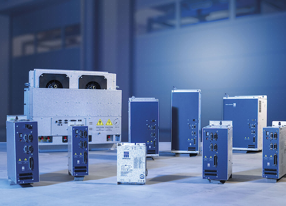
Frequency Converters: Past – Present – Future

Operating Machine Tools & Co. Safely Without Speed Sensors
Feel free to contact us
![[Translate to Englisch:] Frequenzumrichter SD2S](/fileadmin/_processed_/d/1/csm_Header_SD2S_f887eb0cac.png)
Frequency Converter SD2S
Powerful, flexible and compact – these words describe the drive amplifier SD2S by SIEB & MEYER. Using the available drive functions synchronous and asynchronous motors with speeds up to 480,000 rpm can be driven by SD2S, especially in respect of a low motor heating in high-turning motors with small rotor volume. Furthermore, small motor temperatures are the basis for a high machining quality.
Highlights
Extensive Drive Functions
- Function: Freely selectable drive functions, selectable drive functions SVC, V/f-PWM, HS-Block, Servo.
- Advantage: The optimal drive function can be selected depending on the application requirements.
- Benefit: Best system performance.
Universal Motor Encoder Interface
- Function: Resolver, encoder / linear scale (TTL or Sin/Cos), EnDat, Hiperface, SSI, Hall sensor, linear Hall sensor, magnetoresistive sensor, NAMUR sensor.
- Advantage: High flexibility in the choice of the motor encoder interface.
- Benefit: Low system costs, free choice of the motor manufacturer.
Load Indicator
- Function: As standard SD2S offers a highly precise evaluation of the torque-forming current.
- Advantage: The evaluation can be used for tool monitoring. These are for example detection of tool breakage, tool wear, gap eliminator (GAP and crash) and an optimal control of the feed rate during the manufacturing process.
- Benefit: Low system costs, no need of cost-intensive monitoring sensors.
The Specialist for High-speed Applications

Depending on the application, the operation can be carried out with or without encoder. For the operation with an encoder SD2S offers the possibility to evaluate the common encoder systems existing on the market.
SD2S is connected to the higher-ranking control via analog reference values (+/-10 V), digital I/Os, RS232, USB, CAN bus, PROFIBUS*, PROFINET* or EtherCAT (CoE)**.
* Via gateway
**CoE=CAN over EtherCAT
Easy but Robust

Additionally to the basic characteristics in respect of a low motor heating SD2S offers two drive functions characterized by an easy parameterization and a robust operation for applications up to 120,000 rpm. For asynchronous motors the drive function V/f-PWM is used. By means of the V/f characteristic curve the user can carry out the graphically aided parameterization of the motor. As using the V/f characteristic curve is an established form of motor parameterization for example in grinding applications, the user can take advantage of the experience gained in this field.
The SVC drive function (Sensorless Vector Control) is provided for synchronous motors and is based on the equivalent circuit diagram usually found in the motor data sheet. SVC allows 4-quadrant operation of high speed synchronous motors and generators so that SD2S can be used for high speed applications such as turbo blowers or turbines for utilization of process energy.
The Interfaces of SD2 (Two-channel Device)

- Mains supply (DC)
- 24 V-Logic supply
- Parameterization and diagnosis
- 6 digital inputs and 4 digital outputs
- Safety integrated "STO": Restart lock to meet category 4/PL e according to EN ISO 13849-1:2015 and EN 61508:2010 SIL3
- Encoder inputs and outputs (Puls-direction signals)
- Encoder inputs and outputs (measuring system simulation)
- Analog reference value interfaces: +/-10 V
- Resolver inputs
- Thermal contacts
- Universal motor encoder interface: Encoder / linear scale(TTL or Sin/Cos), EnDat, Hiperface, SSI, Hall effect sensor, linearer Hall sensor, magnetoresistive sensor
- SERVOLINK 4 via optical fiber connector
- 2 x Motor connection for synchronous / asynchronous spindles, linear motors and rotary motors
EtherCAT, PROFIBUS and PROFINET via gateway
Drive Functions and Safety Functions
Technology Functions for Grinding Applications

Multi parameter sets
The flexibility of grinding machines largely depends on the possibility of a fast and simple use of grinding spindles. The feature of saving up to 64 motor parameter sets in the drives enables the variable operation with different motors. The number of parameter sets can be encoded via the digital inputs or alternatively via the provided data interfaces.
Gap eliminator / Load indicator
The load indicator is a standard function that is implemented in all devices of series SD2x. The function is used to monitor the status of the active current of spindles. If a preset motor workload is exceeded, the function generates a message. In contrast to acoustic emission sensors, this function evaluates the actual active current of the motor. This is why a very high precision is possible when detecting the load changes of the motor. A load created by e.g. a touch between tool and work piece causes a significant rise in the motor current. Such a load is detected by means of the load indicator. This makes additional external components obsolete.
The load indicator can be used:
- as an indicator for tool breakage
- as a main system in dressing processes
- for a detection with micrometer precision when the tool touches the work piece (gap / touch)
- as an indicator for a necessary tool change due to abrasive wear
- as an indicator for a necessary feed rate reduction (productivity increase by reducing the air-cutting time)
- for a fully automatic adjustment
- as a substitute for acoustic sensor technologies (acoustic emission)
Software for Initial Operation and Parameterization: drivemaster2

The oscilloscope function allows optimization of the axes in the machine via the drive-setup-tool without additional measuring equipment.

The clear design of the software allows intuitive parameterization via graphics and block diagrams. The „Parameter-Wizard“ guides the user step-by-step through the system configuration and allows intuitive setup of the device via help messages and comments.
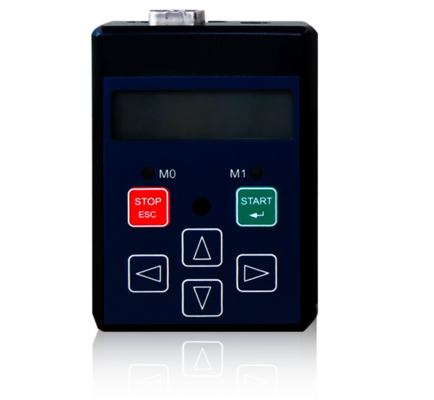
Operation Unit (optional)
LCD status display for the indication of operating data:
- Parameters
- Reference / actual speed
- Load display
- Active spindle
- Error messages
LED status displays for:
- Ready for operation
- Load message
Technical Specifications of Frequency Converter SD2S
| Device type | Rated power1 | Rated current | Peak current/time | Max. output voltage1 | HxWxD (mm) | Weight | Cooling |
|---|---|---|---|---|---|---|---|
| Compact devices - 1 x 50 VAC mains voltage | |||||||
| 0362X40DA | 330 VA | 10 Arms | 14 Arms/5 s | 3 x 45 VAC | 249 x 70 x 188 | 2.5 kg | Air |
| Compact devices - 1 x 110 ... 230 VAC mains voltage | |||||||
| 0362X40DC | 1.5 kVA | 10 Arms | 14 Arms/5 s | 3 x 200 VAC | 249 x 70 x 188 | 2.5 kg | Air |
| 0362X40EC | 1.5 kVA | 10 Arms | 28 Arms/2 s | 3 x 200 VAC | 249 x 70 x 188 | 2.5 kg | Air |
| Compact devices - 3 x 200 ... 230 VAC mains voltage | |||||||
| 0362X41EC | 3.8 kVA (6.9 kVA2) | 20 Arms | 28 Arms/5 s | 3 x 200 VAC | 253 x 104 x 188 | 3.5 kg | Air |
| 0362X41IC | 3.8 kVA (6.9 kVA2) | 20 Arms | 56 Arms/2 s | 3 x 200 VAC | 253 x 104 x 188 | 3.5 kg | Air |
| Compact devices - 3 x 200 ... 480 VAC mains voltage | |||||||
| 0362X40EF | 4.3 kVA | 7 Arms | 28 Arms/5 s | 3 x 410 VAC | 249 x 70 x 232 | 2.6 kg | Air |
| 0362X41EF | 9.7 kVA | 14 Arms | 28 Arms/5 s | 3 x 410 VAC | 253 x 104 x 188 | 3.5 kg | Air |
| 0362X41IF | 9.7 kVA | 14 Arms | 56 Arms/2 s | 3 x 410 VAC | 253 x 104 x 188 | 3.5 kg | Air |
| 0362X49IF3) | 9.7 kVA | 14 Arms | 56 Arms/0,4 s | 3 x 410 VAC | 279 x 90 x 220 | 3.9 kg | Air |
| 0362X45EF | 15.9 kVA | 23 Arms | 28,3 Arms/5 s | 3 x 410 VAC | 390 x 181 x 178 | 7.8 kg | Air |
| 0362X45IF | 20.8 kVA | 30 Arms | 56,6 Arms/2 s | 3 x 410 VAC | 390 x 181 x 178 | 7.8 kg | Air |
| 0362X46IF | 24.2 kVA | 35 Arms | 56,6 Arms/5 s | 3 x 410 VAC | 460 x 190 x 220 | 13.7 kg | Air |
| 0362X46LF | 30.5 kVA | 44 Arms | 70,7 Arms/5 s | 3 x 410 VAC | 460 x 190 x 220 | 13.7 kg | Air |
| 0362X48MF | 55.4 kVA | 80 Arms | 113 Arms/5 s | 3 x 410 VAC | 429 x 272 x 265 | 19 kg | Air |
| 0362X48OF | 55.4 kVA | 80 Arms | 113 Arms/5 s | 3 x 410 VAC | 429 x 200 x 262 | 15 kg | Water |
X = 1: CAN-Bus
X = 2: EtherCAT and CAN-Bus
1) Rated power and max. output voltage for mains voltage/supply voltage (in italic)
2) Output power at three-phase mains
3) NRTL/CSA certified
Technical Specifications of Frequency Converter SD2S light without Interfaces for Measuring Systems, with CAN bus
| Device type | Rated power1 | Rated current | Peak current/time | Max. output voltage1 | HxWxD (mm) | Weight | Cooling |
|---|---|---|---|---|---|---|---|
| Compact devices - 1 x 110...230 VAC mains voltage | |||||||
| 0362120DC | 1,5 kVA | 10 Aeff | 14 Aeff/5 s | 3 x 200 VAC | 249 x 70 x 188 | 2,5 kg | Air |
| 0362120EC | 1,5 kVA | 10 Aeff | 28 Aeff/2 s | 3 x 200 VAC | 249 x 70 x 188 | 2,5 kg | Air |
| Compact devices - (3)1 x 110...230 VAC mains voltage | |||||||
| 0362121EC | 3,8 kVA (6,9 kVA2) | 20 Aeff | 28 Aeff/5 s | 3 x 200 VAC | 253 x 104 x 188 | 3,5 kg | Air |
| 0362121IC | 3,8 kVA (6,9 kVA2) | 20 Aeff | 56 Aeff/2 s | 3 x 200 VAC | 253 x 104 x 188 | 3,5 kg | Air |
| 0362129EC3) | 3,8 kVA (6,9 kVA2) | 20 Aeff | 28 Aeff/1 s | 3 x 200 VAC | 279 x 90 x 220 | 3,9 kg | Air |
| Compact devices - 3 x 200...480 VAC mains voltage | |||||||
| 0362121EF | 9,7 kVA | 14 Aeff | 28 Aeff/5 s | 3 x 410 VAC | 253 x 104 x 188 | 3,5 kg | Air |
| 0362121IF | 9,7 kVA | 14 Aeff | 56 Aeff/2 s | 3 x 410 VAC | 253 x 104 x 188 | 3,5 kg | Air |
1) Rated power and max. output voltage for mains voltage/supply voltage (in italic)
2) Output power for three-phase mains
3) NRTL certified
Applications
About Sieb & Meyer
SIEB & MEYER AG - Drive and control solutions of the latest generation
SIEB & MEYER was founded in 1962 and is a successful company in the field of industrial electronics. With around 300 employees worldwide today, we develop and manufacture control technology and drive electronics. Our core technologies include controllers for mechanical engineering and automation technology, servo amplifiers for a wide range of drives and frequency converters for high-speed motors and generators.
Contact
SIEB & MEYER AG
Auf dem Schmaarkamp 21
D-21339 Lüneburg
Phone: +49 4131 203 0
Fax: +49 4131-203 2000
You can find all sales contacts at: www.sieb-meyer.com/contact/sales
You can find all agencies and partners at: www.sieb-meyer.com/contact/offices-and-sales-partners


