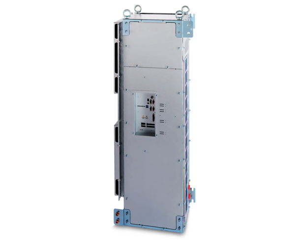
Frequency Converter SD2M Turbo
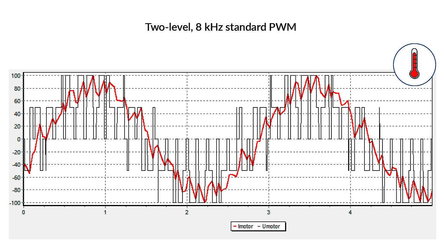
Standard converters in the higher power classes typically use the well-known technology of two-level pulse width modulation (PWM) with max. 8 kHz switching frequency. In most high-speed applications, this requires additional components such as LC filters or chokes to minimize the additional losses in the engine.
Highlights
| Technology/ System-Property | SD2M Three-level PWM | Standard converter Two-level PWM with motor choke | Standard converter Two-level PWM with LC filter |
|---|---|---|---|
| Low weight | ✓ | X | X |
| Small installation space | ✓ | X | X |
| No risk of resonance effects | ✓ | ✓ | X |
| Total costs | ✓ | X | X |
Motor Currents by Comparison
Good to Know
- Currently available power classes from 100 to 500 kVA, with up to 800 Arms rated current
- Liquid cooling as standard (water-based), air cooling on request
- NRTL/CSA certified.
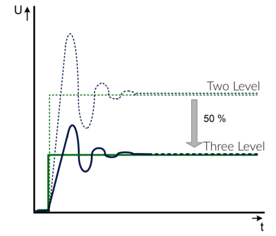
- Reducing the switching PWM amplitude by 50 % leads to very low insulation stress of the motor - even when using long motor cables (see diagram below)
- Optional DC voltage supply for active magnetic bearings via internally fused terminals (intermediate DC circuit)
- Designed for 100 % load 24/7
- All power components are designed for 10 years continuous operation at nominal load
- Designed for worldwide 3-phase supply networks - also IT grids without grounding
- Efficient software drivemaster2 for parameterization and diagnosis
- Customized solutions can be realized
- 3C3 protective coating of the PCBs for operational reliability in aggressive environments
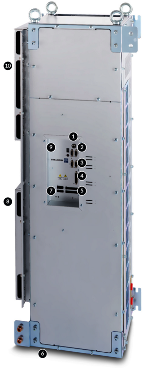
The Interfaces of Frequency Converter SD2M for Turbo Applications
- USB connection, parameterization, diagnosis and operation
- RS232 / RS485 / CAN interface / Modbus
- 2 analog reference value interfaces: +/-10 V, 2 analog outputs: 0 to 10 V
- Universal Motor Encoder Interface: Hall sensor, linear Hall sensor, magnetoresistive sensor, NAMUR sensor (pulse generator), Sin/Cos encoder
- 9 digital inputs and 5 digital outputs
- Liquid cooling
- Safety integrated "STO": Restart lock to meet category 4/PL e according to EN ISO 13849-1:2015 and EN 61508:2010 SIL3
- Motor connection
- 2 TTL encoder inputs and outputs
- Power supply
Drive Functions and Safety Functions
Software for Initial Operation and Parameterization: drivemaster2
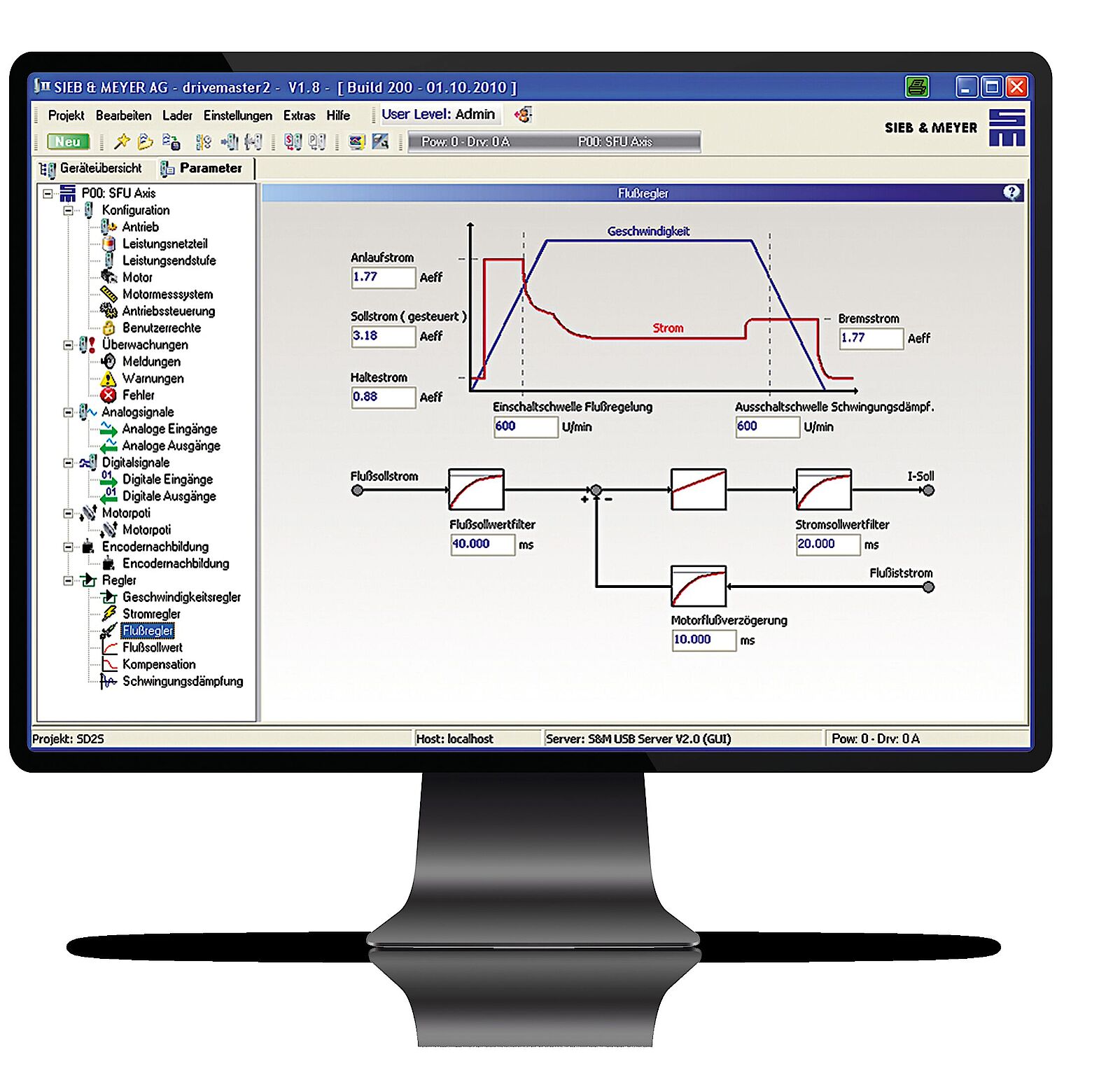
Parameterization
- Tree-type structure
- Block diagrams
- Graphics
- Interactive help messages
- Comments
- „Parameter-Wizard“
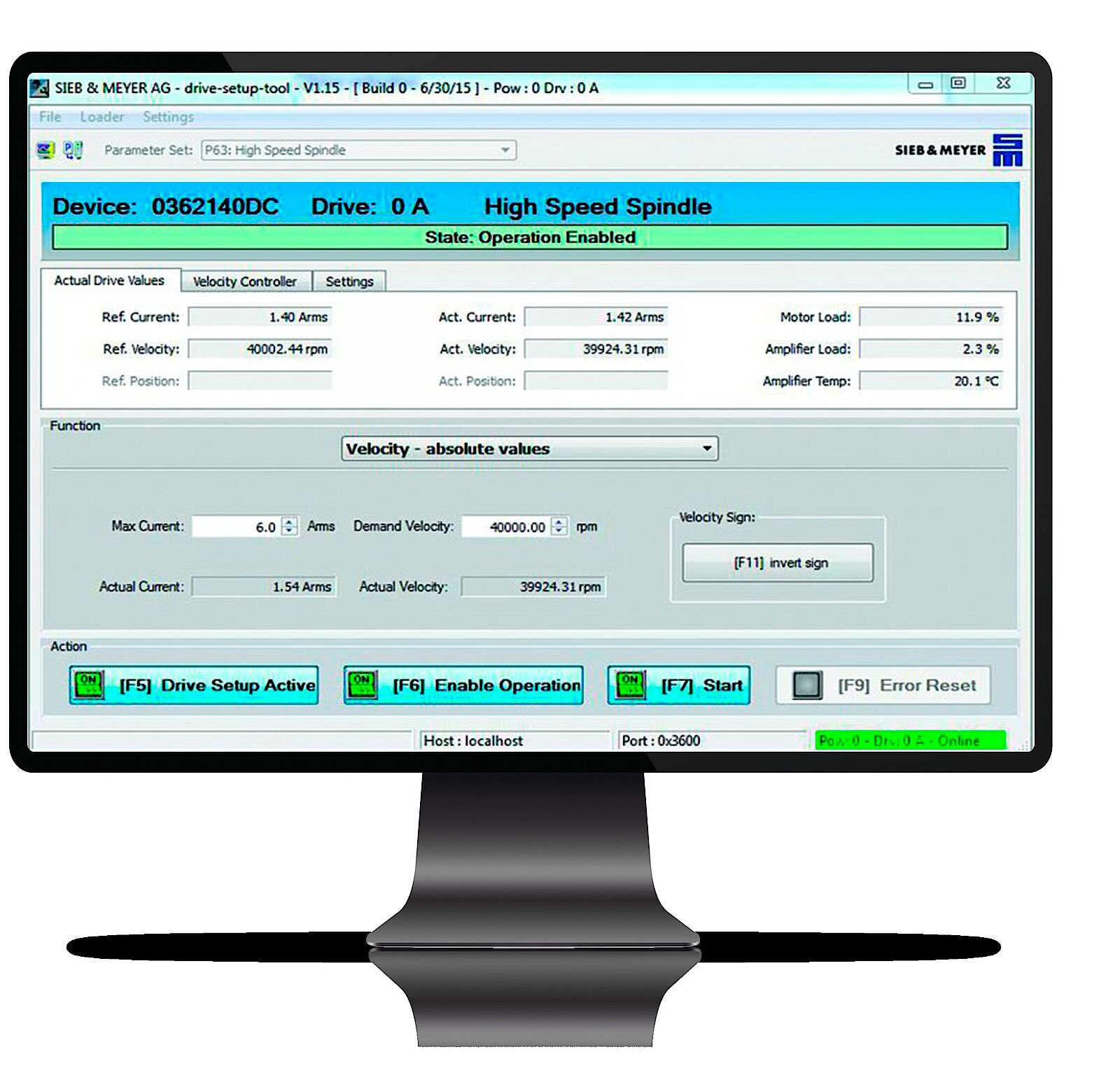
Operation
- Without higher-ranking control
- Visualized reference and actual values
- Error and status messages
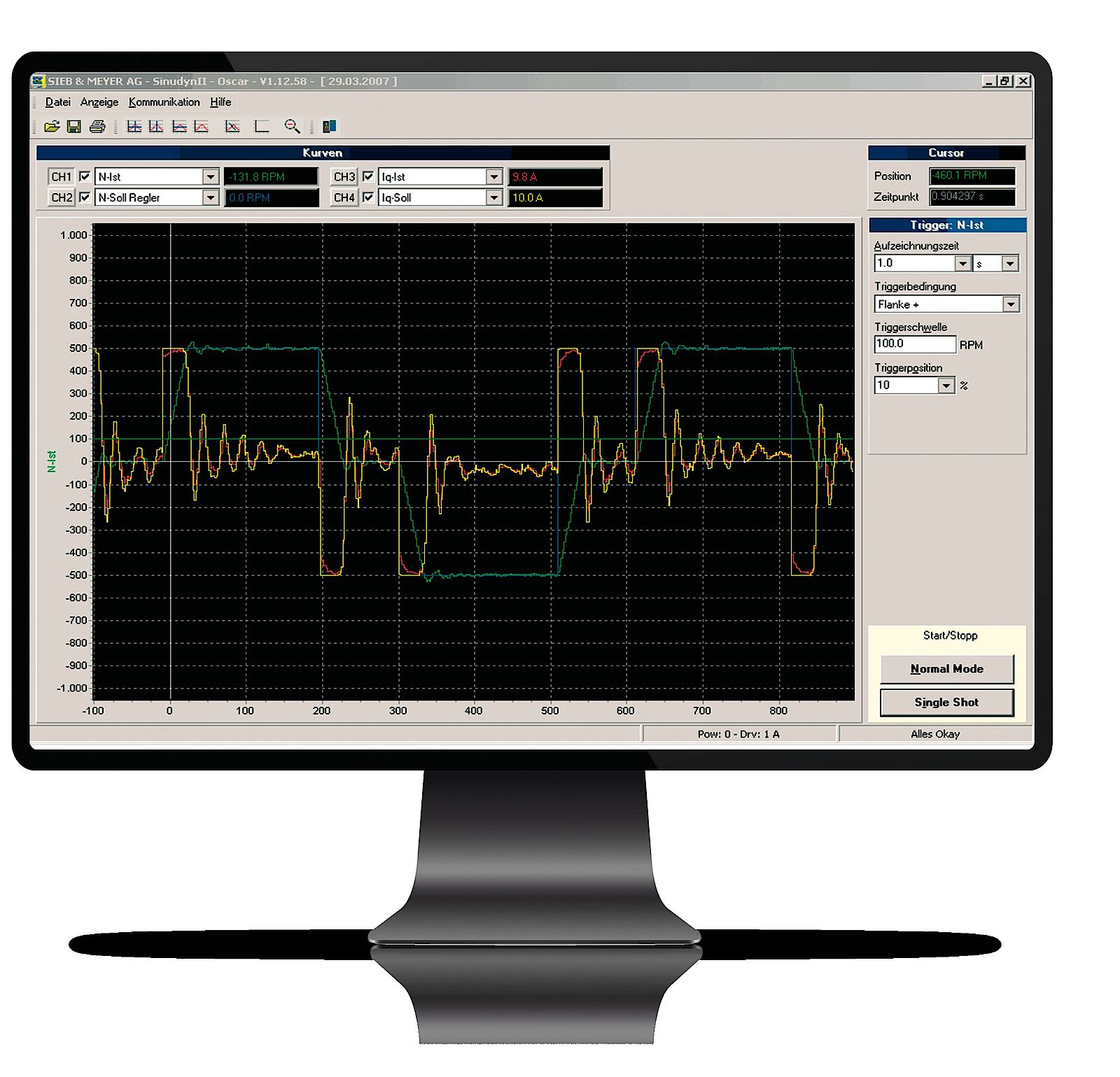
Diagnosis
- 4-channel oscilloscope
- Zoom functions
- Trigger functions
- Long-term recording function
- Measurements can be saved
- Diagnosis of the inputs and outputs
- Bus monitor
Technical Specifications SD2M Turbo
with 3-phase AC Mains Voltage without Break Chopper
Voltage class 400 VAC
Input voltage range 180 .. 528 VAC
| Device type | Mains voltage | Output power (kW) | Output apparent power (kVA) | Output current (A) | Max. output current (A) | HxWxD (mm) | Weight | Cooling |
|---|---|---|---|---|---|---|---|---|
| 0369x71AF0200 | 3 x 400 VAC | 97 kW | 114 kVA @ 16 kHz | 165 A @ 16 kHz 3) | 165 | 685 x 388 x 188 | 30 kg | Water 1) |
| 0369x71BF0000 | 3 x 400 VAC | 72 kW | 83 kVA @ 16 kHz | 120 A @ 16 kHz | 120 | 656 x 545 x 218 | 34 kg | Air |
| 0369x73AF0200 | 3 x 400 VAC | 150 kW | 177 kVA @ 16 kHz | 255 A @ 16 kHz | 255 | 771 x 439 x 207 | 43 kg | Water 1) |
| 0369x73BF0200 | 3 x 400 VAC | 180 kW | 215 kVA @ 16 kHz | 310 A @ 16 kHz | 310 | 771 x 439 x 207 | 43 kg | Water 1) |
| 0369x73CF0000 | 3 x 400 VAC | 115 kW | 132 kVA @ 16 kHz | 190 A @ 16 kHz | 190 | 746 x 629 x 273 | 54 kg | Air |
| 0369x73DF0000 | 3 x 400 VAC | 130 kW | 152 kVA @ 16 kHz | 220 A @ 16 kHz | 220 | 746 x 629 x 273 | 54 kg | Air |
| 0369x75AF0100 | 3 x 400 VAC | 285 kW | 333 kVA @ 16 kHz | 480 A @ 16 kHz | 480 | 1317 x 336 x 489 | 94 kg | Water 2) |
| 0369x75BF0100 | 3 x 400 VAC | 365 kW | 436 kVA @ 16 kHz | 630 A @ 16 kHz | 630 | 1317 x 336 x 489 | 94 kg | Water 2) |
| 0369x75CF0000 | 3 x 400 VAC | 205 kW | 236 kVA @ 16 kHz | 340 A @ 16 kHz | 340 | 1317 x 684 x 374 | 133 kg | Air |
| 0369x75DF0000 | 3 x 400 VAC | 265 kW | 308 kVA @ 16 kHz | 445 A @ 16 kHz | 445 | 1317 x 684 x 374 | 133 kg | Air |
| 0369x76BF0200 | 3 x 400 VAC | 490 kW | 554 kVA @ 8 kHz | 800 A @ 8 kHz | 800 | 1478 x 353 x 596 | 136 kg | Water 1) |
1) Cooling pipes aluminum
2) Cooling pipes copper
0369x: Variant 1 = CAN-Bus / Modbus RTU, Variant 2 = EtherCAT + CAN-Bus / Modbus RTU
News
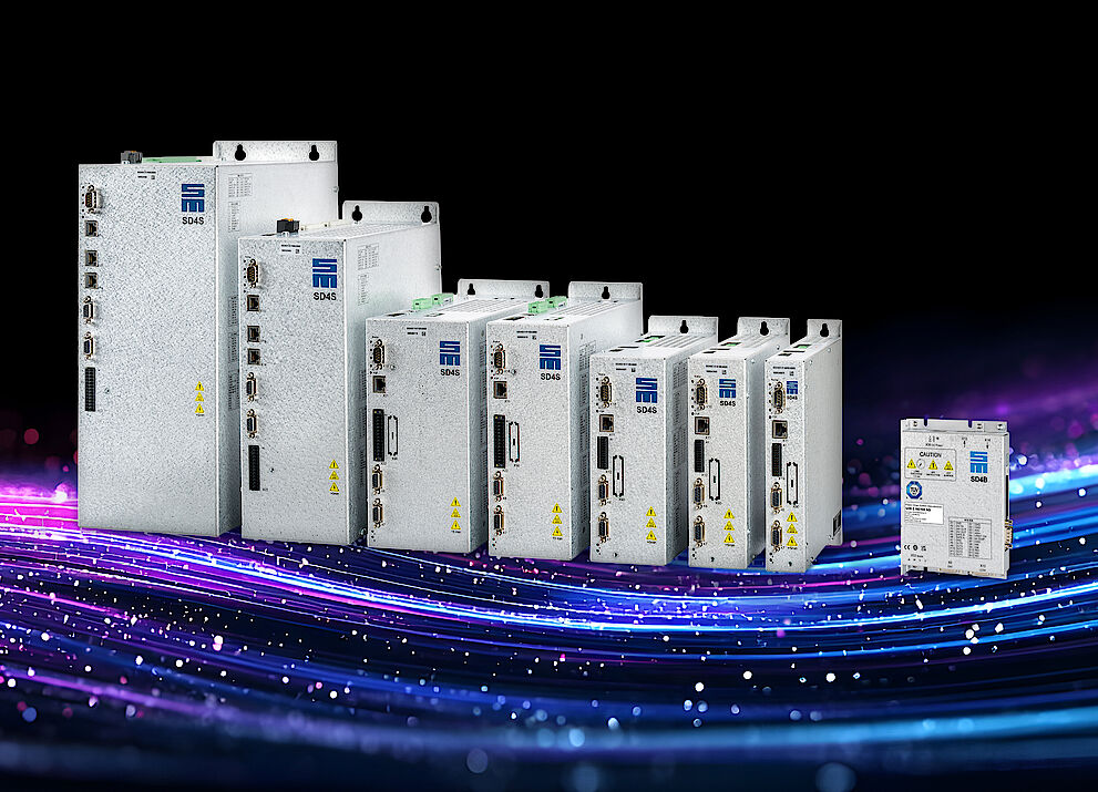
SIEB & MEYER AG Presents SD4x Generation with Innovative Features at the SPS Trade Show 2025
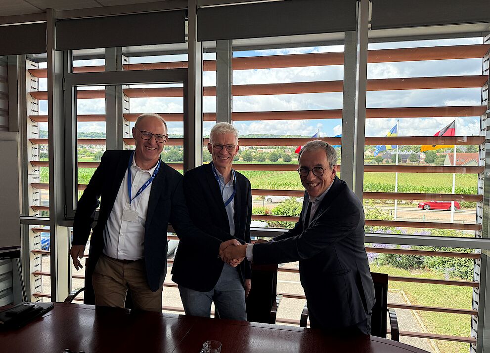
SIEB & MEYER AG and SKF announce collaboration
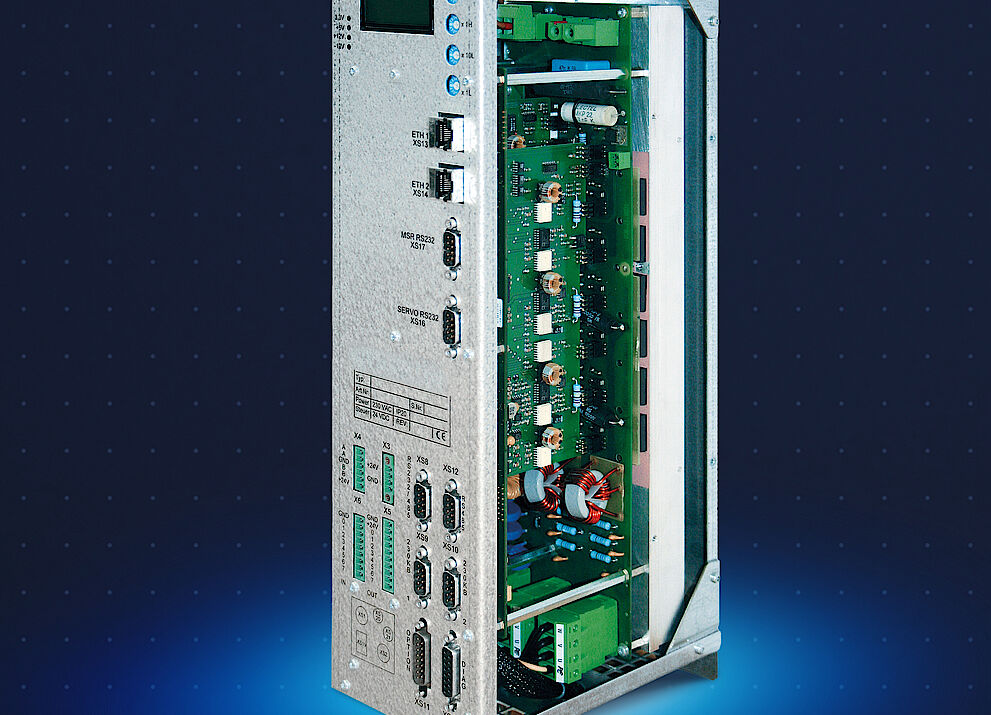
From Simple to Complex
Feel free to contact us
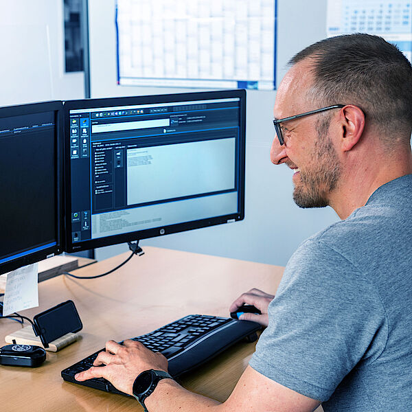
![[Translate to Englisch:] Frequenzumrichter SD2M Turbo](/fileadmin/_processed_/6/d/csm_Header_SD2M_Turbo_e2c3c1a16c.png)
Frequency Converter SD2M Turbo
Standard converters in the higher power classes typically use the well-known technology of two-level pulse width modulation (PWM) with max. 8 kHz switching frequency. In most high-speed applications, this requires additional components such as LC filters or chokes to minimize the additional losses in the engine.
The Booster
SIEB & MEYER frequency inverters are specially designed for high-speed applications and use the three-level technology - also called multi-level technology - which is very advantageous in these applications.
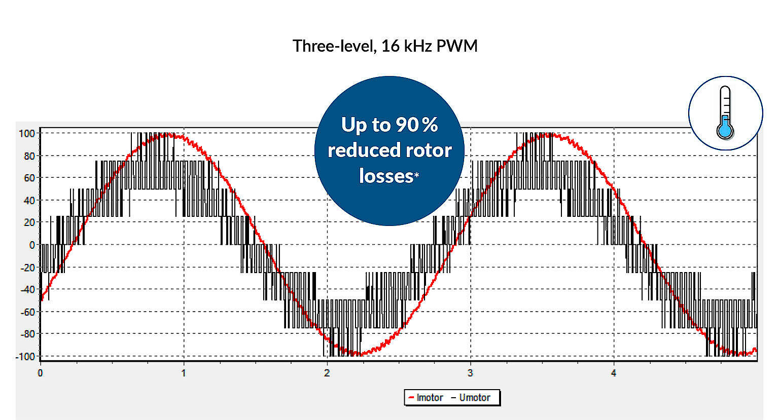
As a rule, no motor filter elements are required when using our SD2M Turbo inverter series. This is due not only to the three-level technology, but also to the fact that we supply PWM switching frequencies of up to 16 kHz as standard. The combination results in a significantly improved motor current quality, which extremely reduces the unwanted rotor losses - by up to 90 %!
| Technology/ System-Property | SD2M Three-level PWM | Standard converter Two-level PWM with motor choke | Standard converter Two-level PWM with LC filter |
|---|---|---|---|
| Low weight | ✓ | X | X |
| Small installation space | ✓ | X | X |
| No risk of resonance effects | ✓ | ✓ | X |
| Total costs | ✓ | X | X |
Highlights
Three-Level Technology
- Function: The output stages of SD2M Turbo are based on a three-level technology and provide rotating field frequencies up to 2,000 Hz with switching frequencies of 16 kHz.
- Advantage: Reduced motor losses combined with minimum efforts for motor filters and motor chokes as well as low interfering radiation and insulation stress.
- Benefit: Low system costs over the whole product life cycle.
Efficiency
- Function: The devices reach efficiencies of up to 98 %.
- Advantage: The high efficiency of the devices ensures optimal system efficiencies and reduces cooling requirements.
- Benefit: Maximum system output and lower environmental footprint due to lower energy consumption.
DC Supply
- Function: Active emergency braking and maintenance of voltage supply in case of power supply failure.
- Advantage: No separate voltage supply for the magnetic bearings needed.
- Benefit: Protection of the magnetic bearings in case of power failure as well as cost savings.
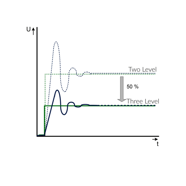
Motor Currents by Comparison


Good to Know
- Currently available power classes from 100 to 500 kVA, with up to 800 Arms rated current
- Liquid cooling as standard (water-based), air cooling on request
- NRTL/CSA certified.
- Reducing the switching PWM amplitude by 50 % leads to very low insulation stress of the motor - even when using long motor cables (see diagram below)
- Optional DC voltage supply for active magnetic bearings via internally fused terminals (intermediate DC circuit)
- Designed for 100 % load 24/7
- All power components are designed for 10 years continuous operation at nominal load
- Designed for worldwide 3-phase supply networks - also IT grids without grounding
- Efficient software drivemaster2 for parameterization and diagnosis
- Customized solutions can be realized
- 3C3 protective coating of the PCBs for operational reliability in aggressive environments
The Interfaces of Frequency Converter SD2M for Turbo Applications
![[Translate to Englisch:] Frequenzumrichter SD2M Turbo](/fileadmin/_processed_/7/8/csm_2500x2500_technische-Details_SD2MTurbo_1bc7dba442.png)
- USB connection, parameterization, diagnosis and operation
- RS232 / RS485 / CAN interface / Modbus
- 2 analog reference value interfaces: +/-10 V, 2 analog outputs: 0 to 10 V
- Universal Motor Encoder Interface: Hall sensor, linear Hall sensor, magnetoresistive sensor, NAMUR sensor (pulse generator), Sin/Cos encoder
- 9 digital inputs and 5 digital outputs
- Liquid cooling
- Safety integrated "STO": Restart lock to meet category 4/PL e according to EN ISO 13849-1:2015 and EN 61508:2010 SIL3
- Motor connection
- 2 TTL encoder inputs and outputs
- Power supply
Drive Functions and Safety Functions
Software for Initial Operation and Parameterization: drivemaster2
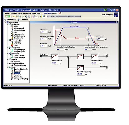
Parameterization
• Tree-type structure
• Block diagrams
• Graphics
• Interactive help messages
• Comments
• „Parameter-Wizard“
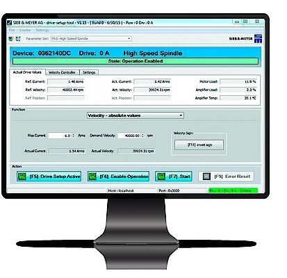
Operation
• Without higher-ranking control
• Visualized reference and actual values
• Error and status messages
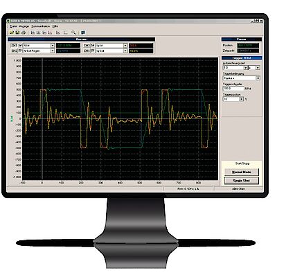
Diagnosis
• 4-channel oscilloscope
• Zoom functions
• Trigger functions
• Long-term recording function
• Measurements can be saved
• Diagnosis of the inputs and outputs
• Bus monitor
Technical Specifications SD2M Turbo
with 3-phase AC Mains Voltage without Break Chopper
Voltage class 400 VAC
Input voltage range 180 .. 528 VAC
Applications
About Sieb & Meyer
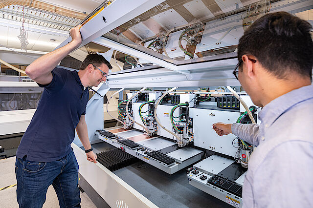
SIEB & MEYER AG - Drive and control solutions of the latest generation
SIEB & MEYER was founded in 1962 and is a successful company in the field of industrial electronics. With around 300 employees worldwide today, we develop and manufacture control technology and drive electronics. Our core technologies include controllers for mechanical engineering and automation technology, servo amplifiers for a wide range of drives and frequency converters for high-speed motors and generators.
Contact
SIEB & MEYER AG
Auf dem Schmaarkamp 21
D-21339 Lüneburg
Phone: +49 4131 203 0
Fax: +49 4131-203 2000
You can find all sales contacts at: www.sieb-meyer.com/contact/sales
You can find all agencies and partners at: www.sieb-meyer.com/contact/offices-and-sales-partners


